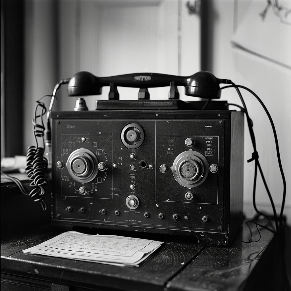
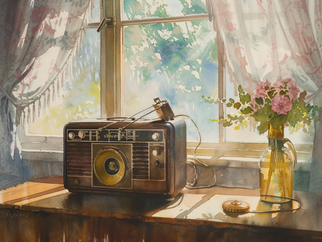
|
|
|
|
Using a Bosch KF161 for APRS
|
 |
|
|
|
|
Currently the Museum has a large number of crystal operated Bosch KF161
mobile transceivers available. As these units have no front panel controls,
they are very useful for APRS purposes. The rigs come with the appropriate
crystal (144.800 MHz) and are fully aligned for the 2m amateur band.
We are able to offer this rig directly from the Museum for the
incredible price of 16 EURO only!
Below are some hints and tips that might be useful when applying the KF161
for APRS use. Thanks to PE1HZG for his textual contribution and PE1NDO for
the clear images.
|
|
Tinytrack
|
 |
|
If you want to use the KF161 for APRS, you need to add a suitable
radio modem. A small modem is available as a DIY kit from the
Tinytrack website (see below). This is a small interface, build
around a PIC microcontroller, that is linked to the rig, the GPS
receiver and (optionally) a PC. On the website, you'll find the
full circuit diagram, the PCB layout and the HEX file for the PIC
controller.
|
|
Insufficient audio level from Tinytrack
|
 |
|
A lot of people have complained that the audio level
from the Tinytrack PCB is too low, resulting in unsufficient
span in the HF output. A simple solution is described on the
Tinytrack website. Replace R6 (220k) by a 100k resistor.
|
|
Squelch doesn't work
|
 |
|
It has been brought to our attention, that the squelch circuit of
some KF161 units doesn't seem to work. This is caused by the fact
that the KF161 units we are using here, don't have any front panel
controls. Instead they were used with a remote control unit.
Some links may therefore be omitted from the rig, preventing the squelch
signal from the IF stage to reach the AF stage.
The solution is rather simple and requires only two wire links.
One existing wire link needs to be moved into another position
and another link has to be added.
The pictures below give a good impression on how to do this.
Click the images to enlarge.
|
|
|
|
|
|
In the first image you'll see 6 holes to the left of the PCB. In the standard
version of the KF161, this is the position for the squelch switch.
To the right of the PCB, 12 holes indicate the position where
the on/off switch normally resides. In this rig, the on/off switch is
replaced by 4 wire links. One link should be added to the position of the
squelch switch (6 holes on the left). One of the 4 wire links on the right
needs to be changed. Please note that the new wire links are shown rather
large in the pictures. This is done for clarity only. It is far better
to mount the wires as close to the PCB as possible.
|
|
Pre-emphasis and De-emphasis
|
 |
|
The KF161 units have been operated in a network with phase modulation (PM).
For Packet Radio application however, frequency modulation (FM) is required.
PM uses the so called pre-emphasis technique, that amplifies the higher
audio frequencies more than the lower ones. In the receiver this effect is
reversed with a de-emphasis circuit. As this effect is unwanted for FM
application, we need to modify the rig somewhat. Fortunately, this is rather
simple and only involves changing and adding a few wire links.
|
|
|
|
|
|
Modification of the transmitter is rather simple as we only have to
add a single wire link to the modulation amplifier (NF SENDEN).
The soldering side of the PCB contains one track with an obvious cut
in it. Next to the cut is the letter F. 'Repair' this track by
soldering a small wire onto it.
|
|
|
|
|
|
|
|
Something similar needs to happen in the receiver. This time we'll have
to change an existing wire link on the receiver PCB (NF EMPFANG).
Locate the letters P and F on the soldering side of the board.
Remove the wire link marked P and connect a wire link at F.
That's all.
|
|
Frequency
|
 |
|
Some rigs seems to suffer from a frequency offset of a couple of kHz.
In some cases this offset is so large, that you can't send or receive
Packet Radio properly. This is generally caused by the aging of the crystal.
Adjustment is rather easy and involves the use of a frequency counter.
Please look inside the rig from the top. A square hole is visible, through
which the PCB of the HAUPTOSCLILLATOR can be accessed. This PCB contains
10 sockets for crystals, only one of which is occupied. Next to the crystal,
you'll find a reed relay and an adjustable coil. Now adjust the core of the
coil. PLEASE NOTE: not to tough the core with a metal object, such as
a screwdriver. The core is likely to break! Use a suitable tool instead,
made of ceramic, plastic or wood. Alternatively, you may want to create one
yourself from a small piece of PCB material.
It is recommended to re-align the frequency again after a couple of months.
This is neccessary because the crystal is likely to age a bit more.
This ageing effect is most noticable during the first few months.
|
|
HF Power amplifier - output level
|
 |
|
The HF output amplifiers have already been adjusted so, under normal
circumstances, it shouldn't be neccessary to re-align them.
If you need to re-align the output amplifier for whatever reason,
please note that it is very important to first put all adjustable
components into the state indicated on the green shields (template).
Next align the circuit from front to back. If you don't follow this
procedure, the output amplifier is likely to start oscillating.
PLEASE NOTE: The output amplifiers have been designed for 6 Watt output.
Although it is possible to obtain higher output levels, this is not
recommended as it will certainly lead to the death of the amplifier
due to overheating. Once aligned, you can use R26 (on the power supply
PCB) to reduce the output to 6 Watt.
|
|
|